Load-bearing capacity of transparent surfaces

The art of structural engineering
– style and safety

When planning a building, not only is it essential to verify the soundness of the main structure, but also the load-bearing capacity of the building envelope. Here we will take at a special new building project – the "Futurium" in Berlin – to illustrate how architects and engineers address the requirements of both structure and design.

The art of structural engineering – some would associate this with historical castles, palaces or cathedrals. Others may think of prominent icons of contemporary architecture, be it bridges, train stations, museums or other comparable constructions. One thing all these examples have in common is that they differ from other art forms in two essential areas. Firstly, buildings are primarily created to fulfil a certain set of functions. Secondly, they differ significantly from other works of art in terms of their dimensions.

The increasing complexity of the functional requirements and the often formidable size of a building project challenges the planner to deal not only with the aspects of design, but also with issues such as the choice of materials, structural planning and production technology. With this in mind, structural engineering can be seen as an art form in which architects and civil engineers work together to create the ideal combination of structure and style.
Over the course of industrialisation, process engineering in steel production took a significant step forward. The materials produced by these new processes (wrought iron and, later, forged steel) were of higher quality and available in larger quantities, which opened up new possibilities for structural engineering. As a ductile and extremely resistant material, steel became the material of choice in buildings with intricate structures and large span widths – and has remained so to this day.

An early example that offered an impressive demonstration of the advantages of this "new" material was the Galerie des Machines in Paris (1889) – a collaborative effort between the architect Charles Louis Ferdinand Dutert and the engineer Victor Contamin. The entire building envelope – which until then would usually have consisted of a solid construction with a minimal number of openings for light and ventilation – was able to be given a light and transparent design using a steel skeleton construction. The result was a look that was truly futuristic for that time.

Not just an excellent structure

The increasing acceptance of the use of skeleton frames in structural engineering inevitably led to a structural separation between the main structure (primary structure) and the building envelope (secondary structure). With the consistent development of new materials and production technologies, the infill of the steel structure with conventional wall elements was gradually replaced by an industrially manufactured, non-load-bearing outer shell, which is hung in front of the load-bearing skeleton and encloses the building like a curtain.

If you look at the early curtain walls of the 1950s or 1960s, you will find impressive examples of highly intricate steel and glass constructions. The planners of the time were all too aware that the curtain wall design, while having many advantages, also presented a number of challenges. With the materials, construction technologies and verification methods available at the time, the complex interplay of static, physical, structural and design requirements could not be fully resolved in the planning process.

The hierarchical division of the main structure and building envelope brought with it the challenge of ensuring that the two structural elements could be connected without penetrating the continuous thermal insulation of the outer shell. Thermally separated profiles and insulating glass were not yet available on the market at that time. It was only as a result of the oil crisis in the 1970s, and the energy requirements that have been steadily in-creasing ever since, that materials and verification procedures were developed to address these issues.
One of the first thermally separated façade systems to enter the market at that time, which has since been continuously developed and has proven its effectiveness in many outstanding projects, is Jansen VISS.

The system, which is based on slim steel profiles, not only offers an excellent supporting structure for large-scale glazing, but also provides the best heat transfer coefficients and can therefore help to achieve the most energy-efficient building envelopes.
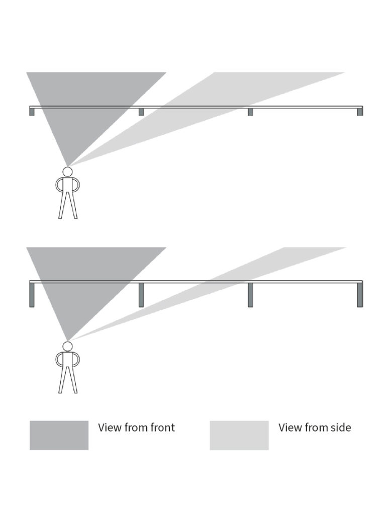
In order to increase the transparency of a glazed façade, the selected frame elements should not only have slim face widths but also a low basic depth. The view through the façade and the amount of natural light are largely determined by the distance between and basic depth of the mullion profiles. Depending on the viewing direction, the basic depth of the frame elements appears greater or smaller and contributes to the perceived width of the profile. Here, unlike most other building materials, the excellent static properties of steel can help to reduce the profile depth and emphasise the transparency of the glazed building envelope.
With regard to the statics of the façade, there are numerous ways to reduce the basic depth of a mullion profile. One option is to fix the profile unilaterally rather than the usual joint fixing – provided that this is permitted by the static structural edge conditions at the installation site. This method significantly reduces the required moment of inertia of the profile under transverse load (wind load). At this point it is also worth noting that the required moment of resistance remains unchanged. That makes this approach particularly suitable for building situations in which verification of the static conditions largely depends on the permissible level of deformation (serviceability limit state).

Because the steel material can be welded, components can be fixed quite elegantly in terms of the design. The steel mullion is welded to a console plate, which is anchored to the shell using bolts. The welded joint can be reinforced with additional ribs, depending on the static requirements. Another option for reducing the basic depth is to create a multi-span beam. With this approach, one mullion profile can extend over several floors and is usually anchored to the floor slabs using sliding bearings.

This gives rise to various structural and physical issues, for example with regard to the deformation of the floor slabs or sound transmission between different sections of the building, which must be taken into account in the planning. In principle, this static approach is feasible if, in a multi-storey room (e.g. an atrium), a horizontal, static support is put in place in front of the reinforced concrete columns of the primary structure, which then acts as an intermediate support.
2.3 x 5
metre big glaces
33 x 12
metre high glacing facades

Optimised light conditions

Using the façade construction of the Berlin Futurium as an example, we will now take a look at the design possibilities offered by the Jansen VISS façade system. The plan was to create a futuristic building that would accommodate exhibitions and events on the subject of "shaping the future". A central aspect of this will undoubtedly be digitalisation, and it was clear to the architects that this topic would dominate the changing exhibitions.

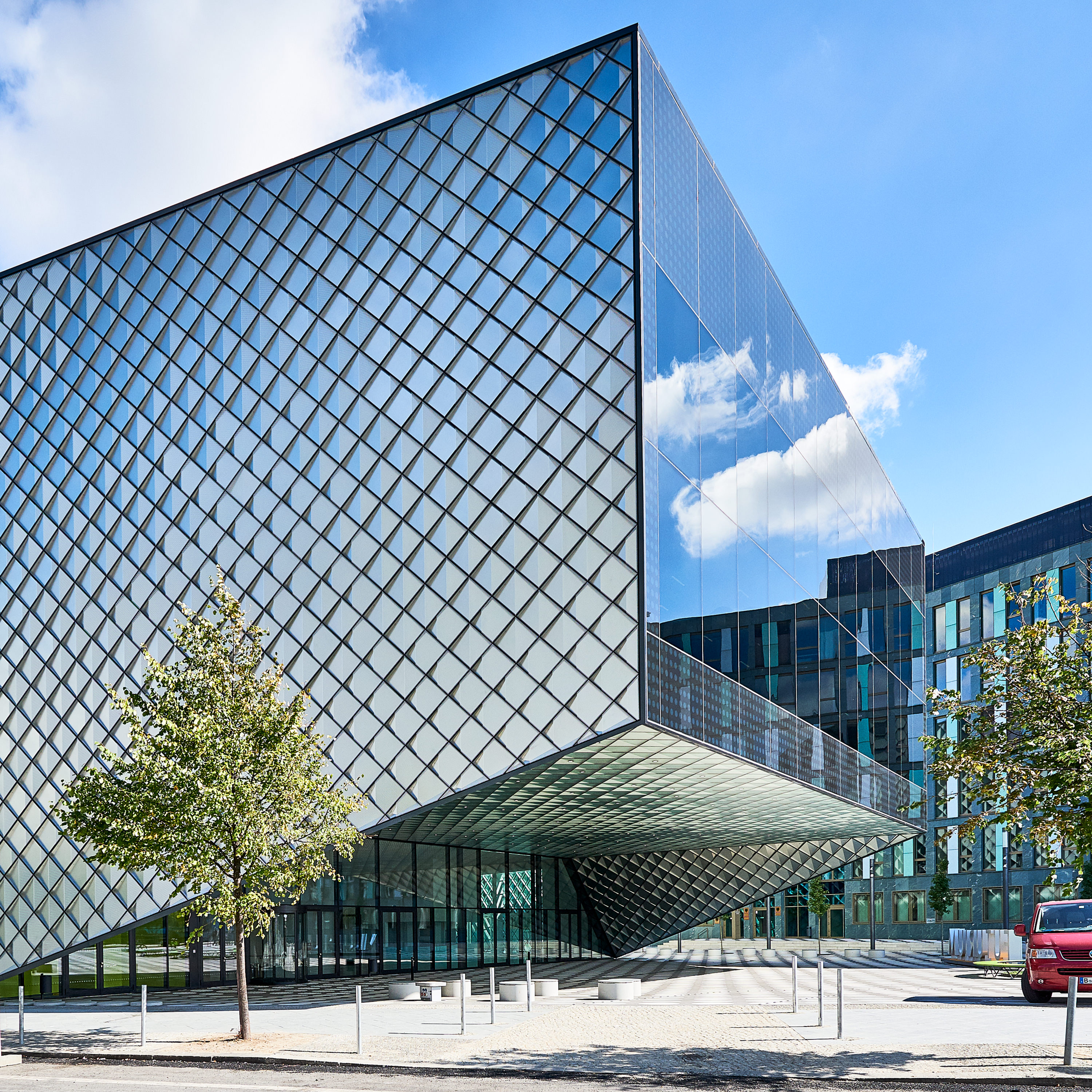
With this in mind, they not only developed the silvery shimmering façades consisting of special glass tiles, but also – as a stark contrast to this small-scale structure – two large steel and glass façades were installed, which act as screens. The surroundings are reflected on these screens, with the scene changing according to where the viewer is standing.

The first floor of the building forms a single, cohesive space. The screens provide natural lighting and offer the visitor an unobstructed view of the government district and the hustle and bustle of the city. In order to optimise both the amount of daylight and the view, there was a clear planning goal to minimise the post and mullion construction of the glass façades, which are up to 33 m wide and up to 12 m high. As well as testing the effects of wind load and the dead weight of the triple insulating glass units with panes measuring up to 2.3 x 5.0 m, it was also necessary to ensure the highest class of fall protection for crowd safety.

It was essential to ensure the serviceability of the bonded glass façade with regard to wind loads and fall protection, taking into account the possibility that the bonding could fail. At the same time, any components used to secure the glass panes mechanically were not allowed to be visible from the outside, as this would impair the visual appearance of the screens. The requirements for the screen façades were therefore as follows:

• Structural glazing façade
• Triple insulating glazing
• High-quality sun shading glass
• Extremely heavy glass (up to 870 kg)
• Minimal profile geometry
• Fall protection
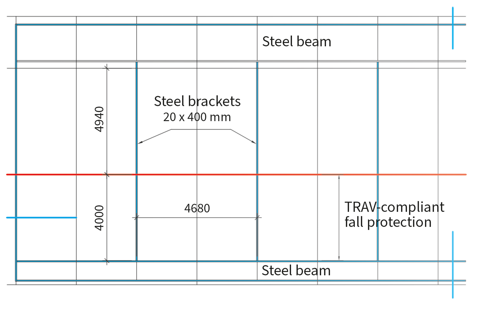
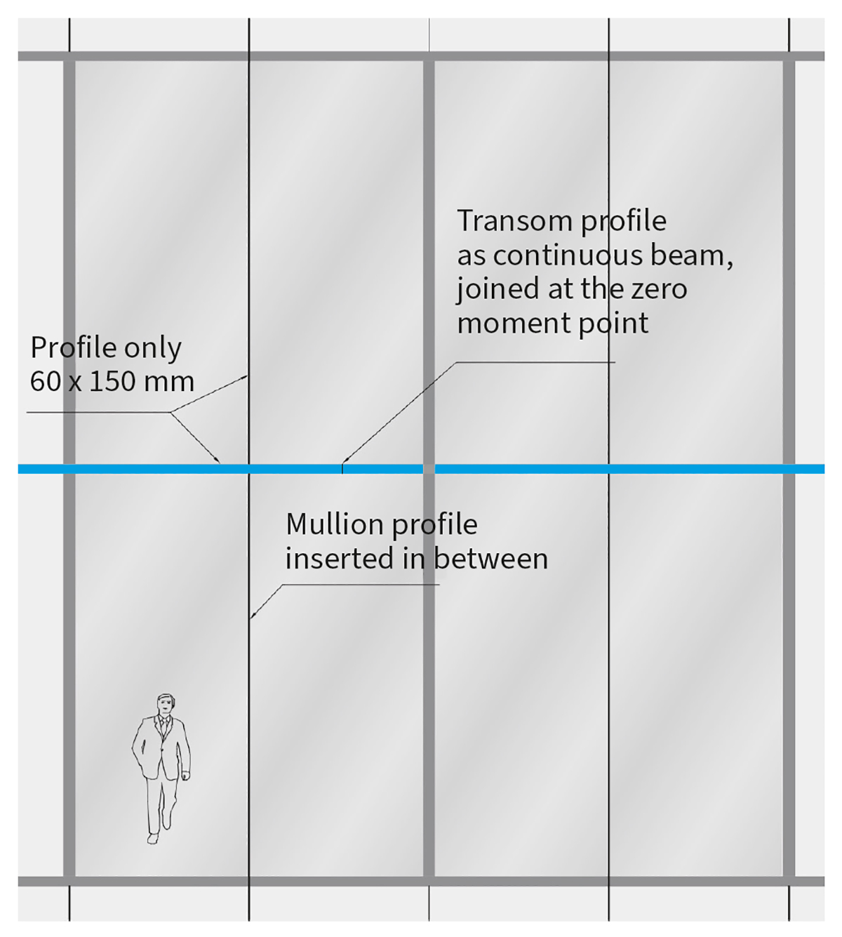
All of these requirements were able to be met with the Jansen VISS SG façade system. Unlike conventional post and mullion constructions, this system diverts the load effects in two ways. The horizontal wind load is transferred via the continuous transom profiles to the steel brackets behind. The mullion profiles are inserted between the continuous transom profiles with non-positive-locking connections, which allows them to transfer the dead weight of the façade to a truss in the roof area.
This also means the exhibition space on the first floor is free from supports, because the cantilevered ceiling in the area of the transparent screens is suspended from the roof structure using steel brackets. These steel brackets act as intermediate supports for the continuous transom profile – an example of how the profile cross section can be optimised by creating a multispan beam. This principle is illustrated in the following drawings of the south façade. This approach resulted in a profile geometry of just 60 x 150 mm, with steel brackets with a cross section of 20 x 400 mm positioned in every second axis.
When optimised in this way, the profile cross sections ensure a large amount of natural light and the most unobstructed view possible. The fall protection requirement is guaranteed by the glass structure, the façade structure and the anchoring between the glass and frame elements.

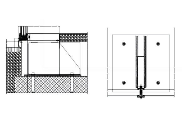
In the Jansen VISS SG façade system construction, the anchoring is performed by a stainless steel glazing clip, which clips into a special opening in the laminated pane. In this specific application, special glazing clips were developed which are perfectly designed to meet the static structural requirements of this extraordinary façade structure – yet another example of the successful union of structure and style.
Considering the requirements described, the visual and structural design of the screens is a prime example of the art of structural engineering. Last but not least, creating the perfect building angle where four surfaces meet, despite all the construction tolerances, is nothing short of a masterpiece – and the Futurium features four of them.